Design for Manufacturability With Rigid Flex PCBs
Rigid Flex PCBs
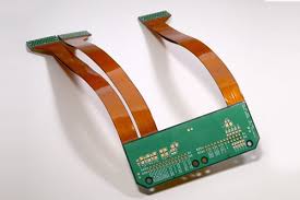
Rigid flex PCBs combine rigid and flexible circuit board technologies to deliver stability, strength, and reliability. The combination of rigid and flex boards helps to reduce the number of connector components on the end product, speed up assembly, and lower costs. However, the construction of rigid flex PCBs introduces additional challenges that require thoughtful deliberation to overcome. These include:
The layer stack-up, dielectric spacing, and the drill chart must be carefully considered to ensure your rigid flex pcb meets electrical requirements while achieving mechanical functionality and manufacturability. It is important to bring your electronic contract manufacturer (ECM) onboard early in the design process so they can help you develop a rigid flex PCB that meets all of your requirements and specifications.
With the rise of mobile devices that have a requirement to bend, flex, or fold, rigid-flex circuit boards have become an industry standard. Rigid flex boards provide a platform for integrating bending areas into the printed circuit board without having to attach individual cable assemblies, which is a more efficient and cost-effective option. Rigid-flex PCBs are used for camera circuits in smartphones and tablets, screen signal connections on laptop computers, industrial control panels, aerospace rotating axes, and many other applications that require flexible components.
Design for Manufacturability With Rigid Flex PCBs
Rigid flex circuits have different fabrication and manufacturing processes than rigid-only PCBs, which is why it’s so crucial to work with your ECM early in the process. They can help you select the right materials for your rigid flex design, which is essential for ensuring that the final product performs as expected and can be manufactured with high yields and low cost.
Once the Gerber files are complete, the next step in the manufacturing process is to create a pattern for the copper laminate that contains the circuitry. To do this, rigid-flex manufacturers either dip the laminate in an etch bath or spray it with an etch solution. Once the copper is etched, the etch resist is stripped using high-speed drilling tools, such as Excimer YAG or CO2 lasers.
The resulting bare copper on the rigid-flex board is then drilled to create pads and vias. The holes are plated through, which is a step that requires extreme precision and care to ensure all of the copper is correctly positioned. During this phase, the fabricator also deposits solder mask onto the bare copper to protect it from contaminants and simplify the assembly process.
To reduce stress across the board, it’s a good idea to stagger traces. This reduces the likelihood of a failure due to excessive strain and stress placed on the circuit during bending and provides added stiffness, which is beneficial for reducing the risk of components detaching from the board.
The last major step in the manufacturing process is to finish and test the rigid flex circuit board. The ECM will use a variety of testing equipment to verify that all of the conductive paths are functioning properly and that there are no issues with signal quality. This includes checking polarity, impedance, and signal integrity.